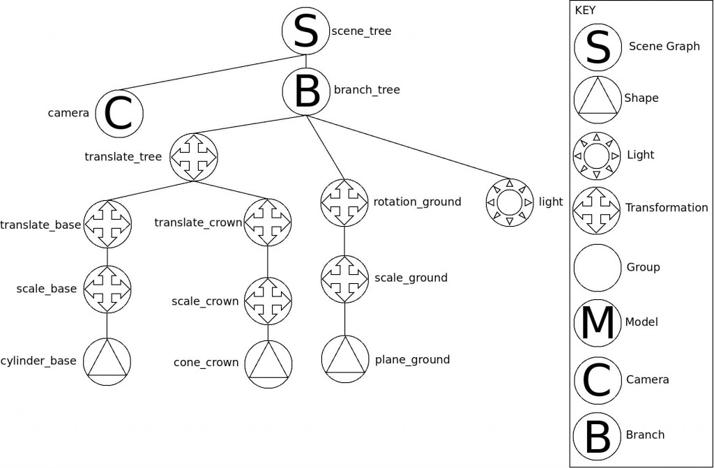
1) Build complex objects at the origin. The origin of the scene is the point (0, 0, 0). All objects are drawn at the origin and will remain there unless they are attached to a transformation node. Finding the correct combination of transformations needed to build complex objects can be tricky. In Figure 1 below, I built a tree using a set of transformations and a couple simple shapes. Basically, I placed a cone on top of a cylinder to create a pine tree.
2) Understand the scene. First, find some graph paper. I recommend drawing an x-z axis in the middle of the paper to determine where you want to place objects in the scene. This works well for scene graphs that have objects placed on a horizontal plane. For example, after the tree in Figure 1 was constructed, I translated it by the vector (200, 0, -100). I only moved it to demonstrate how this could be done. Imagine how many transformations it would take to make an entire forest!
3) Figure out what groups of models and shapes will be loaded and unloaded together. Making the right decision about model grouping is important for high performance. Phantom (graphics engine) calls these groups of models “branches.” If you have unique units in a game that load in waves, each wave might be a branch. This would allow you to unload old units and texture data as the game progresses. It would also allow you to load new models as the game changes. It’s an incremental approach to graphics memory management.
4) Don’t forget about the camera and lighting! At the moment, Phantom supports one camera and any number of lights (e.g. directional or positional).
5) Turn your scene graph into a diagram and then an XML representation.
Figure 1 – Tree Scene Graph
Tree XML Scene Graph
<?xml version="1.0"?> <scenegraph name="scene_tree"> <branch name="branch_tree"> <translation name="translate_tree" x="200.0" y="0.0" z="-100.0"> <translation name="translate_base" x="0.0" y="5.0" z="0.0"> <scale name="scale_base" x="5.0" y="5.0" z="5.0"> <shape name="cylinder_base" type="cylinder" color="brown" /> </scale> </translation> <translation name="translate_crown" x="0.0" y="15.0" z="0.0"> <scale name="scale_crown" x="15.0" y="15.0" z="15.0"> <shape name="cone_crown" type="cone" color="green" /> </scale> </translation> </translation> <rotation name="rotation_ground" ray_x="1" ray_y="0" ray_z="0" angle="90"> <scale name="scale_ground" x="1000.0" y="1000.0" z="1000.0"> <shape name="plane_ground" type="plane" color="gray" /> </scale> </rotation> <directional_light_source name="light" x="20.0" y="300.0" z="20.0" /> </branch> <camera name="camera" cop_x="0" cop_y="0" cop_z="0" vrp_x="20" vrp_y="150" vrp_z="20" vuv_x="0" vuv_y="1" vuv_z="0" /> </scenegraph> |
Sample Video of Tree Scene Graph
Brief Description of Scene Graph Nodes
Scene Graph – The root node of any scene graph
Shape – Simple geometric shape (e.g. triangle, cube, sphere, etc…)
Light – Lights up the scene. There are two different kinds of lights: directional and positional
Transformation – Rotation, translation, or scale operation. Rotation operations spin objects around a given ray. Translation operations move objects
Group – A basic node that doesn’t do anything special, except that it can have any number of child nodes.
Model – A complex object that contains shapes, other models, and meshes. These are often produced by 3D modeling tools.
Camera – The location and orientation of the viewer.
Branch – Used for grouping models and shapes that are loaded and unloaded from memory together
Finally, I wanted to thank Dennis Mikkelson for teaching me the basics of scene graphs when I was an undergraduate. I wish I still remembered the lighting equations he taught us. 🙂
